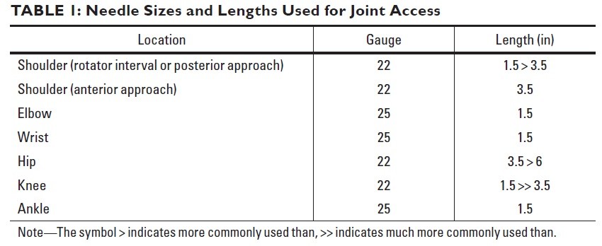
Needle Sizes and Lengths Used for Joint Access
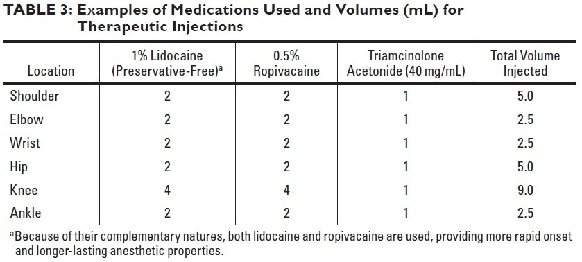
Examples of Medications Used and Volumes (mL) for Therapeutic Injections
Shoulder
Rotator Interval Approach
Arm at the side with the palm up to move the biceps tendon away.
Avoidance of biceps long head tendon by targeting spot on humeral head below top of glenoid with shoulder externally rotated. When level above bottom of coracoid is targeted, injection passes above subscapularis. Contrast medium flows away from needle and fills joint recesses.
Biceps tendon passes through rotator interval before passing into bicipital groove. Radiologist can move biceps out of needle path by having patient externally rotate shoulder. Target is superior medial quadrant of humeral head, between 1- and 2-o'clock positions for right shoulder and 3–5 mm in from edge of cortex.
AC Joint
Elbow
Lateral Approach

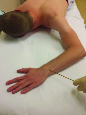
Patient position. Patient lying in prone position on the fluoroscopy table with the arm over the head and elbow in 90° of flexion, thumb up, head turned to side. Metallic pointer is placed in the midpoint of the radiocapitellar joint
25-gauge needle placed into space between radial head and capitellum. When needle enters joint, it may feel like needle is passing into block of cheese. Contrast medium flows away from needle tip into joint.
Posterior Approach

Patient position. Patient lying in prone position on the fluoroscopy table with the arm over the head and elbow in 90° of flexion. Metallic pointer is placed 1 cm above the apex of the olecranon, paramedian lateral to avoid n. ulnaris.
Needle directed toward posterior humeral cortex within olecranon fossa. Some authors advocate central approach traversing triceps tendon; we prefer approach that starts lateral to tendon and heads centrally. Contrast medium should flow quickly away from needle tip. Contrast medium is evident in coronoid fossa in anterior aspect and within joint recess around radial neck.
Elbow is flexed, and a point is marked just above and lateral to the olecranon. The needle is advanced until it contacts the olecranon fossa of the humerus
Wrist

Posteroanterior wrist radiograph shows target sites for different compartments. Yellow indicates radial side of radiocarpal joint; dark green, ulnar side of radiocarpal joint; blue, distal radioulnar joint; light green, four-corners approach to midcarpal compartment; orange, alternative approach to midcarpal compartment.
Radiocarpal compartment injection
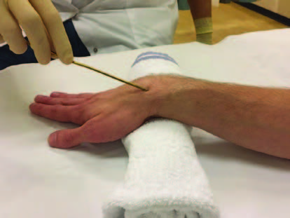
Patient lying in prone position with the arm over the head. The wrist lying on a small pillow, 15° wrist flexion and ulnar deviation, to maximise the size of the dorsal joint space making needle placement easier.

Needle targeting proximal cortex of scaphoid. If cortex is struck within few millimeters of joint space, contrast medium flows into joint; that is, needle does not have to be perched between distal radius and scaphoid. If there is concern about pathology on radial side of wrist, proximal triquetrum can be targeted instead.
Distal radioulnar joint (DRUJ) injection
Patient lying in prone position on the fluoroscopy table with the wrist over the head and the palm down. The target site for the injection is the ulnar aspect of the space between the distal radius and ulna.

Needle tip targeting radial edge of ulna at level of physeal scar and veering into joint after making contact with bone. Contrast medium fills DRUJ and blankets head of ulna. Small amount of contrast medium has passed through perforation in triangular fibrocartilage complex and lies within radiocarpal joint (arrow).
Midcarpal compartment injection

Needle targeting four-corners location between hamate, capitate, lunate, and triquetrum. In this case, contrast medium not only fills midcarpal and common carpometacarpal compartments, which is normal, but also extends into radiocarpal joint and DRUJ, implying interosseous ligament tear and triangular fibrocartilage complex tear, respectively.
Hip
Anterior approach

Patient lying on the fluoroscopy table in supine position with the hip positioned with neutral or slight internal rotation (relaxed anterior musculature and capsule).
Needle being advanced toward lateral aspect of femoral head-neck junction. When needle contacts bone, it is inside joint capsule. Jiggling or twisting needle helps to penetrate last layer of capsule. Contrast medium fills joint. Constriction of capsule at level of midfemoral neck is zona orbicularis, which is thick portion of capsule that should be avoided during needle placement.
Knee
Lateral subpatellar approach

Needle driven into space between patella and anterior femur, starting at about equator of patella. If anesthetic is injected as needle advances, when needle enters joint, anesthetic begins to flow quickly. This is usually near center of patella.
Ankle
Medial clear space approach.

Approach to upper half of medial clear space is straightforward. This approach avoids anterior tendons, major nerves, and dorsalis pedis artery.
Palpate and estimate the entry medial to the tibialis anterior tendon.
Subtalar Joint Injection
Lumbar Facet Joint and Nerve Injection
Lumbar Facet Joint Injection
The C-arm is then rotated ipsilaterally to the side of injection to obtain an oblique view. In this view, the outline of the “scotty dog” is clearly evident.
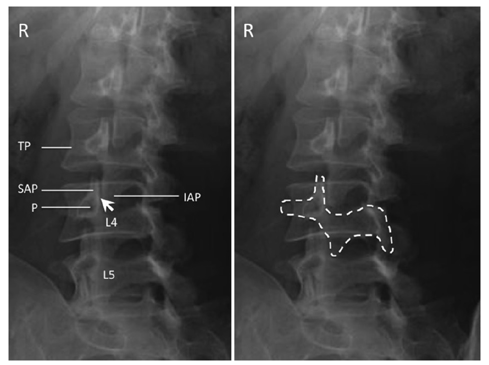
Oblique radiograph of the lumbar spine. The left figure shows the individual structures: SAP superior articular process, IAP inferior articular process, P pedicle, TP transverse process; facet joint is indicated by the arrow . The right figure shows the “scotty dog” appearance of the same structure.
Oblique view is obtained until the joint space formed between the articular processes is optimally seen. A 22-gauge spinal needle is inserted with coaxial technique. A small amount of contrast (0.2 mL) is injected to confirm the intra-articular placement. A volume of 0.5–1 mL injectate (20 mg methylprednisolone or triamcinolone) is sufficient.
Medial Branch Block
The target is the junction of the superior border of transverse process with the superior articular process. Alternatively, another end point has been described, which is the midpoint between the mamilloaccessory notch and the target point just described.
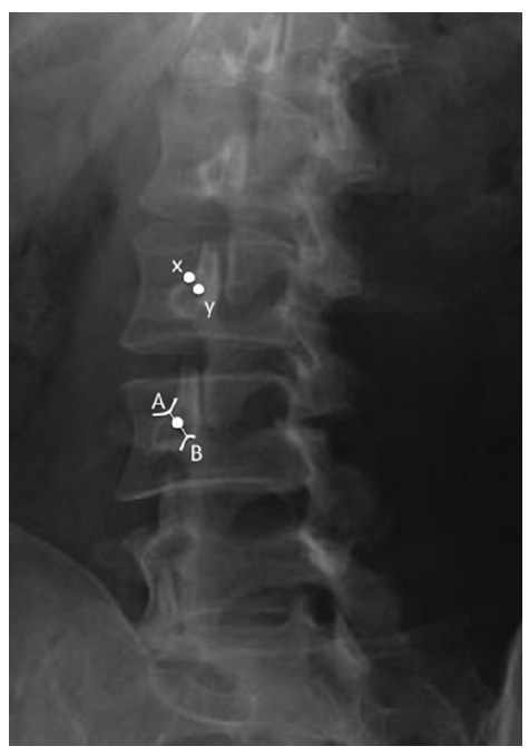
The radiograph shows the target points ( white dots ) for facet medial branch injection. A The junction of the superior border of transverse process with the superior articular process. B The mamilloaccessory notch. x The conventional target which is the junction of the superior border of transverse process with the superior articular process. Y The midpoint between A and B.
L5 Doral Rami Block
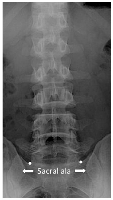
The target points for L5 dorsal rami was indicated by the white dots, which are the ala of the sacrum at the base of the superior articular process of sacrum.
For the L5 dorsal rami block, the target point is the ala of the sacrum at the base of the superior articular process of sacrum in an anteroposterior view
SI Joint
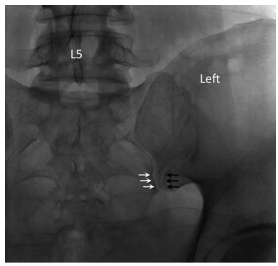
Straight posteroanterior X-ray of the sacroiliac joint. In this view, both anterior ( black arrows ) and posterior joint ( white arrows ) lines are seen. The posterior joint line ( white arrows ) is usually the
more medial one.
The patient is placed in prone position. The C-arm is placed initially in neutral position. The target point is the inferior, posterior aspect of the joint, approximately 1–2 cm cephalad of the most inferior end. In this view, both anterior and posterior joint lines are seen and the posterior joint line is usually the more medial one.
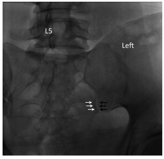
Contralateral oblique X-ray of the sacroiliac joint. The anterior and posterior joint lines aligned to form a crisp silhouette of the joint.
The C-arm is rotated and adjusted until the medial cortical line of the medial silhouette is maximally crisp, which coincides with the beam directed into the posterior opening of the inferior joint space. Usually, this view is obtained with 5–20° of contralateral rotation.
A 22- or 25-gauge spinal needle is used and directed toward initially to the sacrum first to appreciate the depth required. Once the bone is contacted, the needle is redirected toward the joint line. The operator should note the depth of the initial contact so that the needle should not penetrate a few more millimeters deeper than this depth.
Once the needle has entered the joint space, 0.3–0.5 mL of contrast is injected. In posteroanterior view, the contrast material should be seen traveling rostral along the joint (Fig. 48.7 ). A lateral X-ray should be used to confirm the needle position (Fig. 48.8 ). The joint volume in asymptomatic individual is approximately 1.6 mL but is about 1.08 mL in patients requiring SIJ injection. Thus,
the injectate is usually 1 mL.